1. What is Computer Networking?
Computer Networking is the process of connecting two or more computers or devices so they can communicate and share data, resources, and services with each other.
| Network | Coverage | Example |
|---|---|---|
| PAN | Around 10 m | Bluetooth, Smartwatch |
| LAN | Building/Home | Home Wi-Fi, Office |
| MAN | City | City-wide network |
| WAN | Country/World | Internet |
2. Basic Terms
| Term | Simple Meaning |
|---|---|
| Client | Requests data from a server. |
| Server | Provides data or services to clients. |
| Peer | Acts as both a client and a server. - Torrent file sharing. |
| Host | Any device connected to a network. |
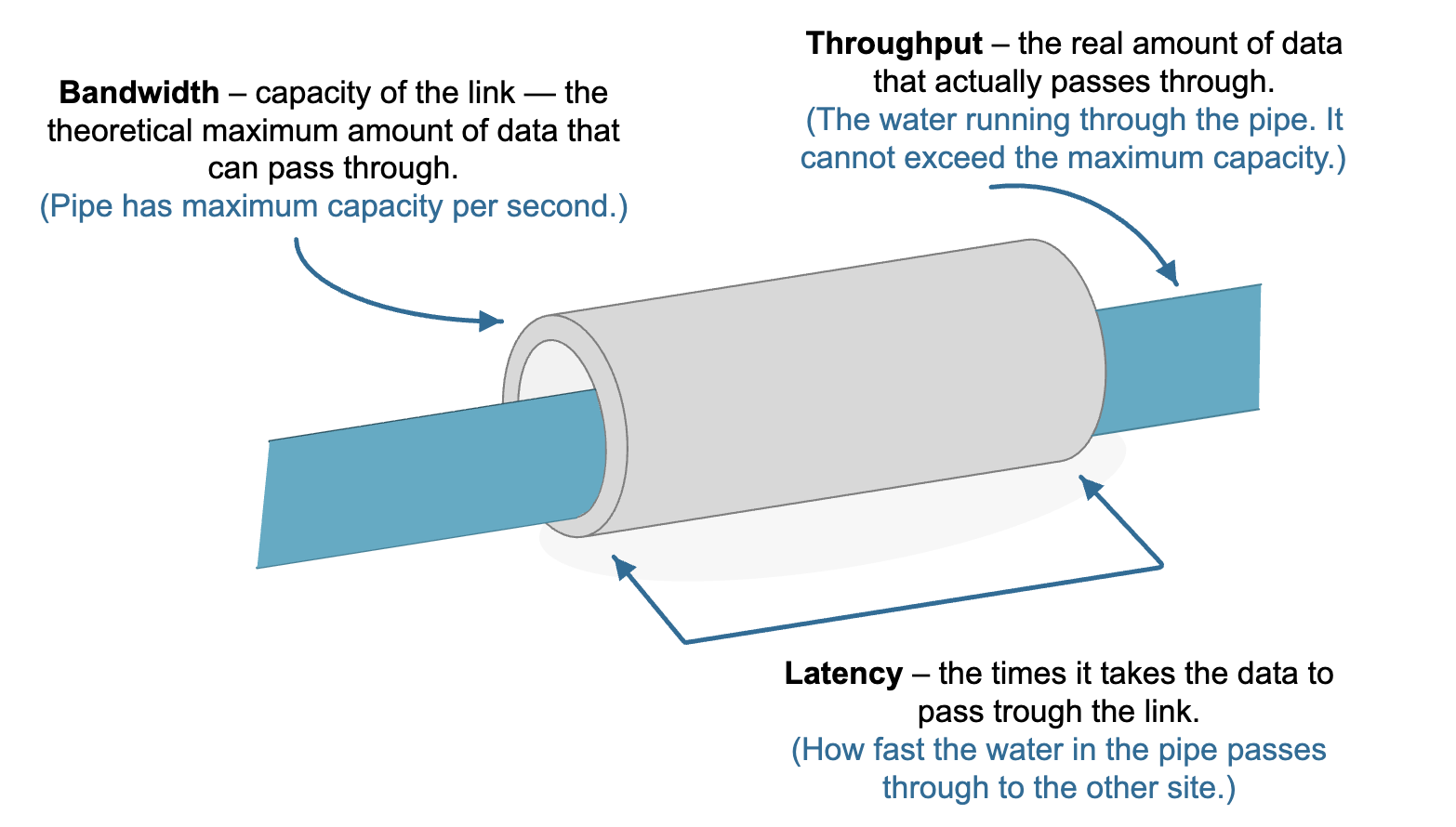
| Bandwidth | Maximum network capacity. Max amount of data that can be transfered |
| Jitter | variation in the time taken by packets to reach the destination - High jitter affects voice calls, video calls, and online gaming. |
| Packet | Small unit of transmitted data. |
| Frame | Data Link Layer unit containing a packet. |
| Localhost | Your own computer (127.0.0.1). |
| Bitrate | Actual data transfer speed. |
| Noise | Unwanted signal interference. |
| Attenuation | Signal becomes weaker with distance. |
| Distortion | Signal changes shape during transmission. |
3. What’s difference between The Internet and The Web ?
The Internet is the global network that connects computers, while the World Wide Web (WWW) is a service on the Internet used to access websites through web browsers. other services like www is email, FTP, Voice Call etc. www use HTTP protocol
Network Devices
- Repeater → Regenerates and amplifies weak signals to extend the communication distance. (Layer 1)
- Hub → Connects multiple devices and broadcasts incoming data to all connected devices. (Layer 1)
- Bridge → Connects two LAN segments and filters traffic using MAC addresses. (Layer 2)
- Switch → Connects devices within a LAN and forwards data only to the destination device using MAC addresses. (Layer 2)
- Router → Connects different networks and forwards packets using IP addresses. (Layer 3)
- Gateway → Connects networks that use different communication protocols by performing protocol translation.
- Modem → Converts digital signals to analog and analog to digital signals to connect a network to an ISP (Internet Service Provider).
- Access Point (AP) → Connects wireless devices to a wired LAN by providing Wi-Fi access. (Layer 2)
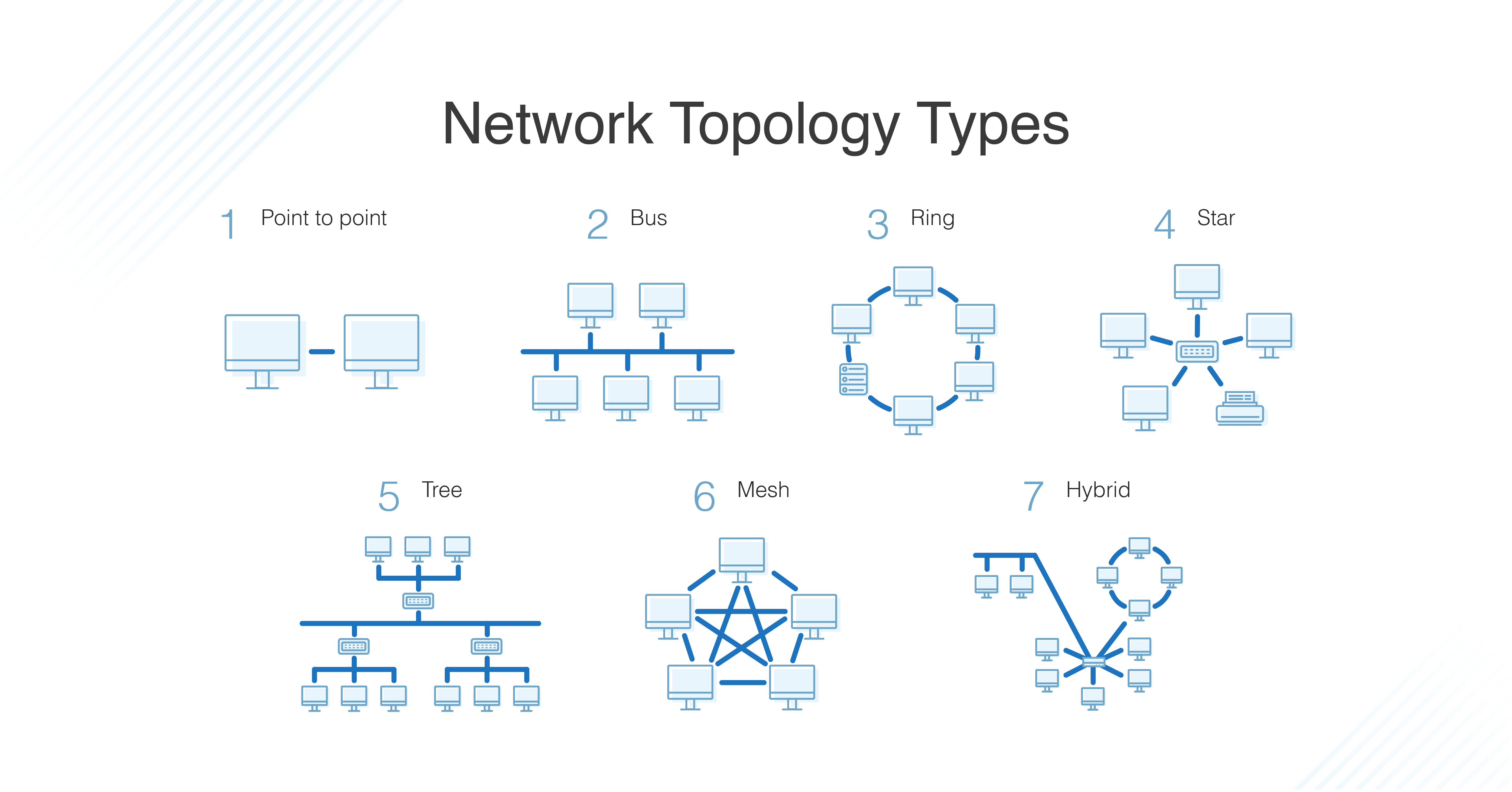
4. Network Topology
5. OSI Model
Data Encapsulation in Networking
The data ==must be encapsulated with additional information==
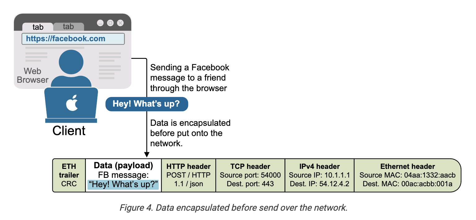
The OSI model, or Open Systems Interconnection model, is a framework that breaks down the encapsulation process into seven layers. Each layer has a specific role and handles a part of the encapsulation, such as data formatting, logical addressing, routing, physical addressing, or error checking.
The following example shows how data moves through the OSI layers and gets wrapped at each step before being sent over the network to the next device. Notice that each layer adds its own specific header with relevant information for the network function.
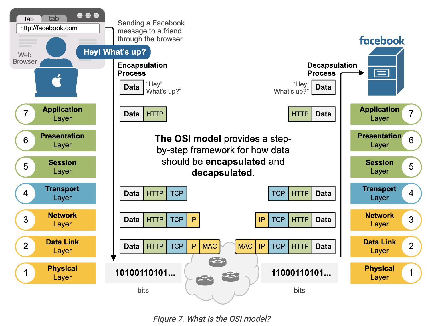
Network device ==cares only for the headers up to a particular layer== and doesn't care about the rest of the headers in the message. For example, a switch only cares about the data link (layer 2) header, which consists of the source and destination MAC addresses. A router cares only about the layer 2 and layer 3 headers, and so on.
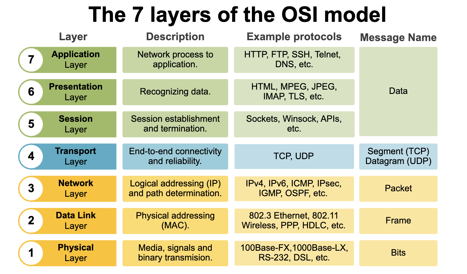
The OSI model vs. TCP/IP model
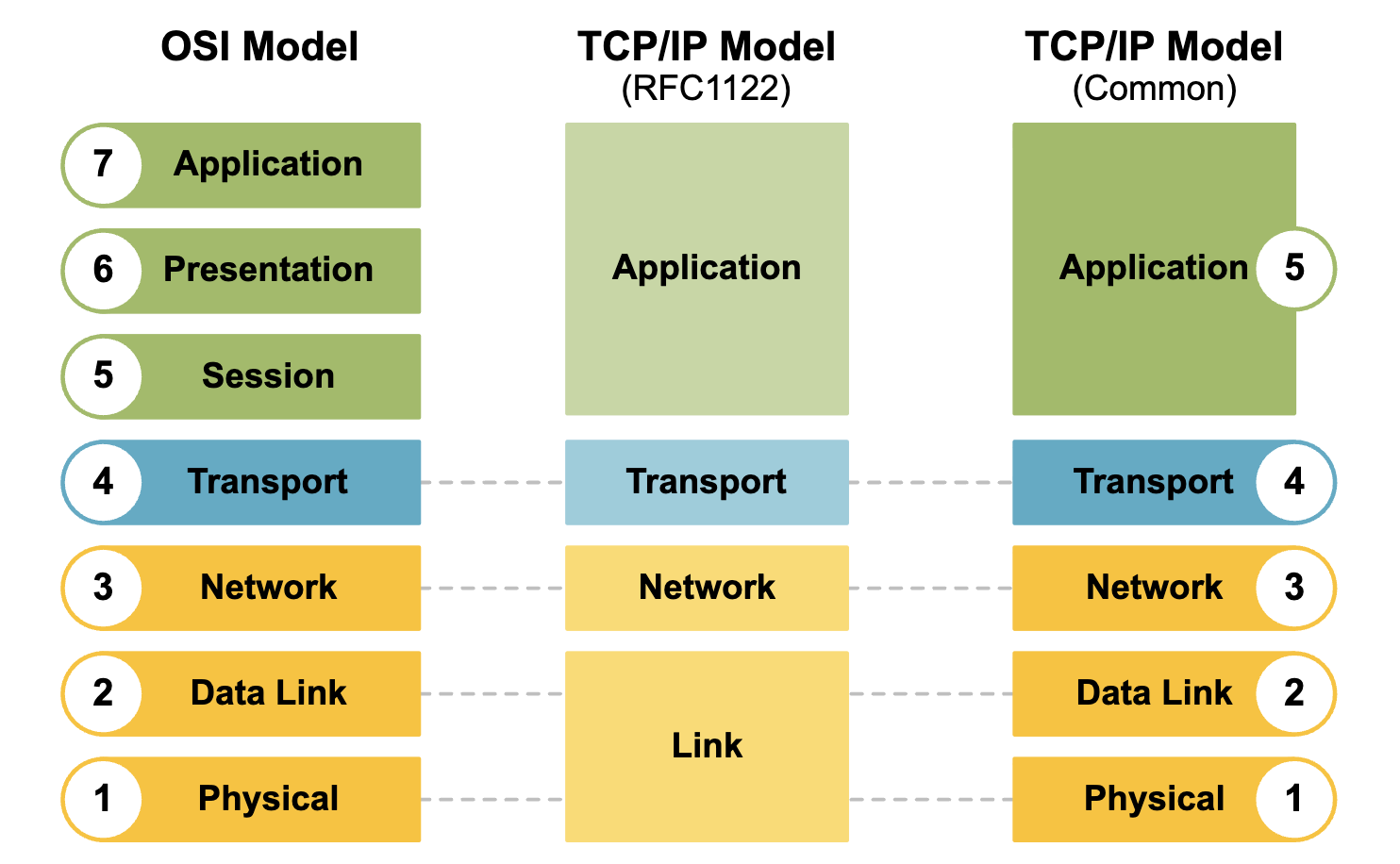
The OSI model, with its seven layers, is a well-structured and useful way to understand ==how data encapsulation works==. However, network engineers quickly notice that layers 5, 6, and 7 are not directly related to most networking tasks. These layers focus more on how software applications handle data, which is usually outside the scope of networking.
As a result, network professionals, through practice and real-world experience, began using a simpler model that focuses on the aspects that matter most to networking—Layers 1 through 4. This led to the development of the TCP/IP model, which has fewer layers and is more aligned with how networks actually operate.
Application Layer
When two computers communicate, they must follow the same protocols. ==A protocol is a set of rules== (like a language rulebook) that defines how to format, send, and receive data.
Presentation Layer : It prepares data before it reaches the application.
- Encryption (keeps data secure)
- Decryption (converts encrypted data back)
- Compression (reduces data size)
- Data format translation (e.g., ASCII ↔ Unicode)
Session Layer : It manages communication sessions between two devices.
- Establishes a session
- Maintains the session
- Terminates the session
| Protocol | Full Form | What It Does | Port |
|---|---|---|---|
| HTTP | HyperText Transfer Protocol | Transfers web pages (not secure) | 80 |
| HTTPS | HTTP Secure | Secure web browsing using SSL/TLS | 443 |
| FTP | File Transfer Protocol | Uploads and downloads files | 21 |
| SFTP | SSH File Transfer Protocol | Secure file transfer | 22 |
| SMTP | Simple Mail Transfer Protocol | Sends emails | 25 |
| DNS | Domain Name System | Converts domain names to IP addresses | 53 |
| SSH | Secure Shell | Secure remote login and command execution | 22 |
| DHCP | Dynamic Host Configuration Protocol | Automatically assigns IP addresses | |
| IMAP | Internet Message Access Protocol | Reads/synchronizes emails from the server |
How HTTP Works
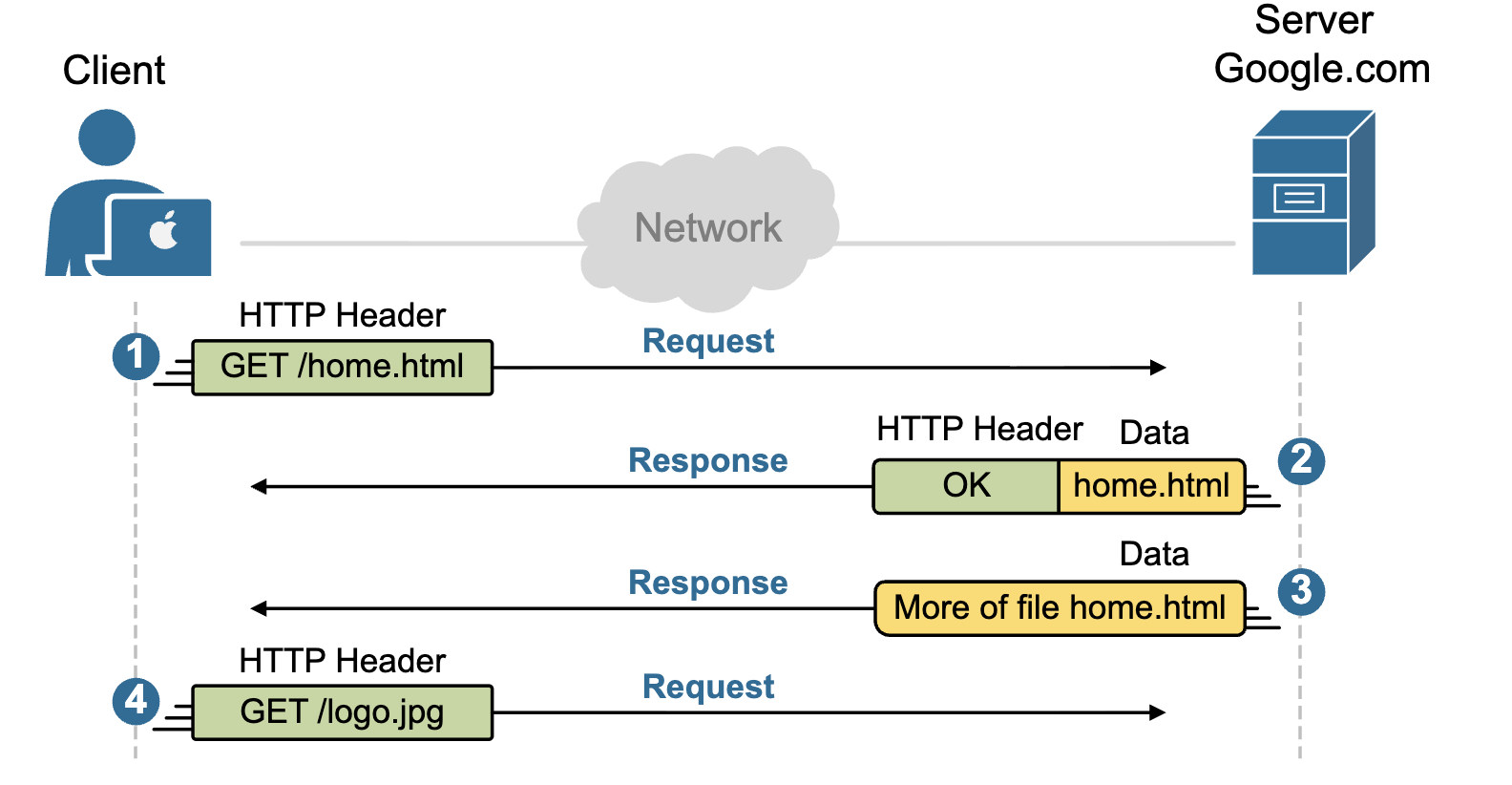
GET REQUEST, POST REQUEST
- The key takeaway of this lesson is to remember that the application layer gives programs ==the rules they need to use the network==.
- It defines how applications request and receive data.
- It also determines how apps encode and decode data. Key protocols at the application layer include HTTP, DNS, SMTP, FTP, SSH, SNMP, and DHCP.
Transport Layer
- TCP is used when ==reliability and data order== matter.
- UDP is used when ==speed and low latency== are more important than perfect delivery.
Each protocol in the OSI model has its own header that it puts on the packet during the data encapsulation process. Since the data encapsulation process starts from the top (layer 7) to the bottom (layer 1), the application layer determines whether TCP or UDP will be used at the transport layer. Therefore, depending on the application, the packet is encapsulated with a TCP or UDP header.
KEY NOTE: Each OSI model layer serves the one above it. The application layer serves the user.
TCP header
The TCP header contains information used to ensure the reliable delivery of data. It includes the following fields, as shown in the diagram below:
- Source and destination ports (to identify applications).
- Sequence and acknowledgment numbers (to track and confirm data receipt).
- Flags (such as SYN, ACK, and FIN) that control the connection state.
- Window size for flow control.
- Checksum for error checking.
- Optional fields for additional features.
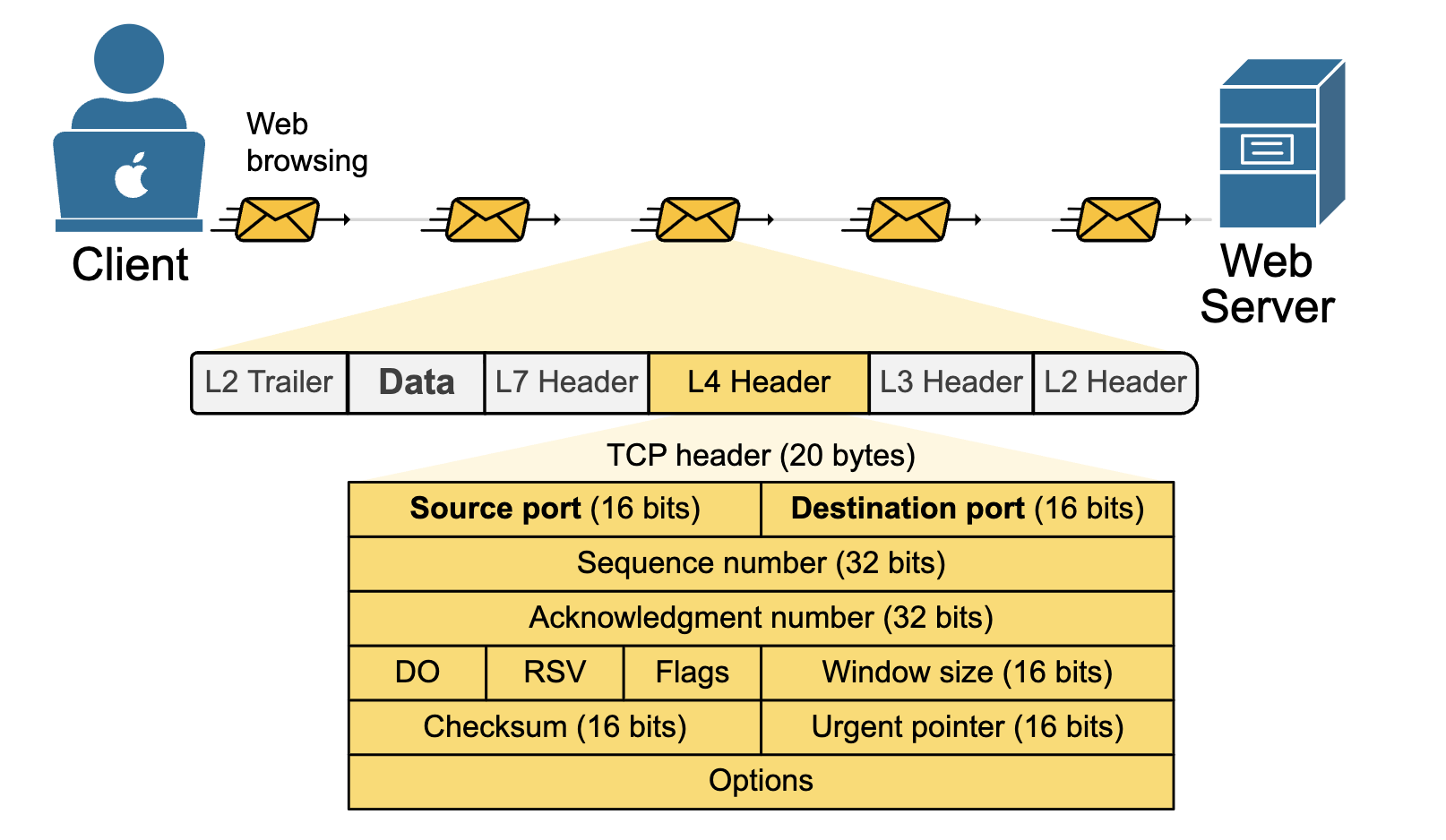
TCP has so many fields in the header because it is designed to manage the connection between two hosts and ensure the ==reliable delivery of data==. That's why it is referred to as a connection-oriented protocol. The most commonly used TCP header is 20 bytes long, but it can grow up to 60 bytes if options are used.
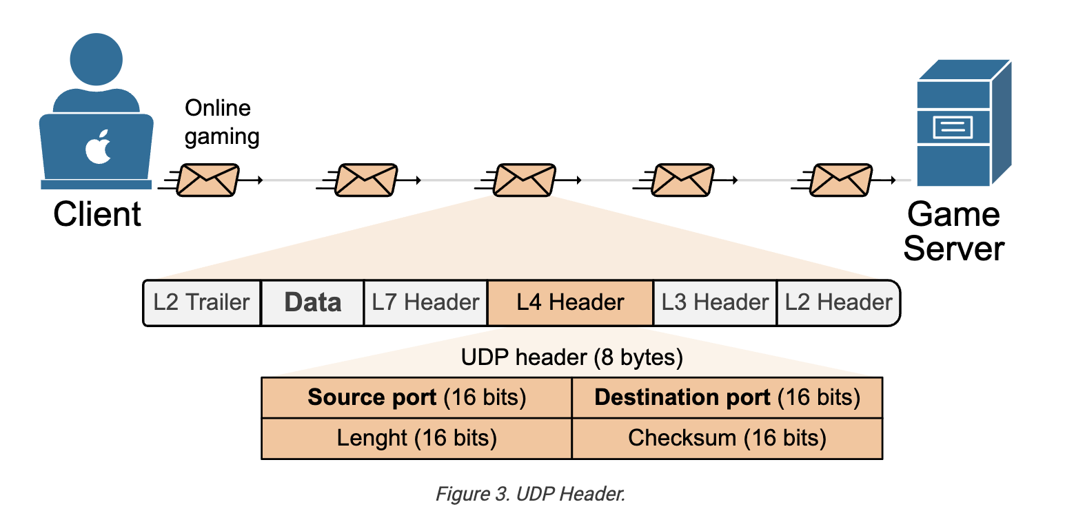
The UDP Header
The UDP header is much simpler. It has a fixed size of 8 bytes. It contains only four fields, as shown below:
- Source and destination ports (to identify applications).
- Length (total size of the UDP header and data).
- Checksum (used for basic error checking).
What are the primary functions of the Transport Layer?
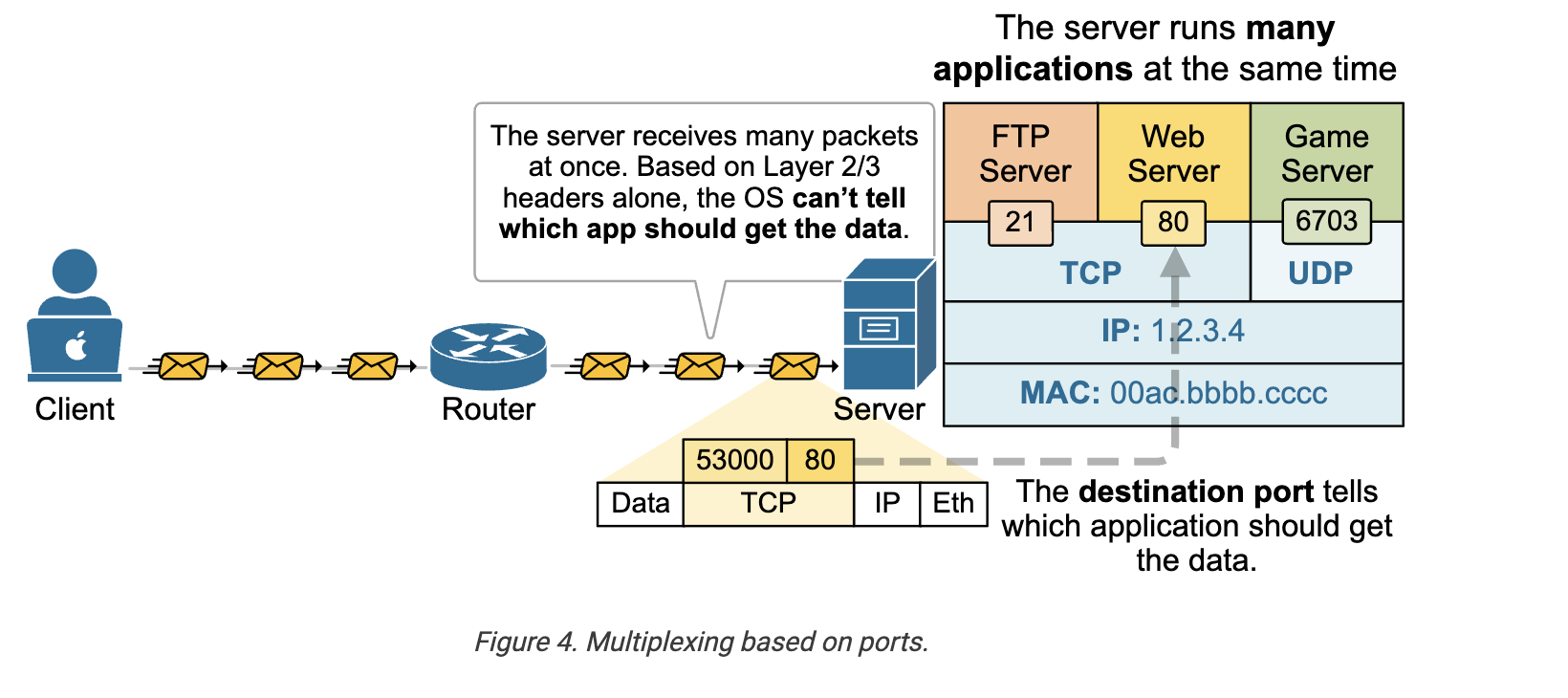
Multiplexing :
First and foremost, the transport layer header is used ==to identify the application== that sends and receives the data over the network. This is the function of the source and destination ports.
- The source port identifies which application on the sender’s device created the data.
- The destination port tells the receiving device which application should receive the data.
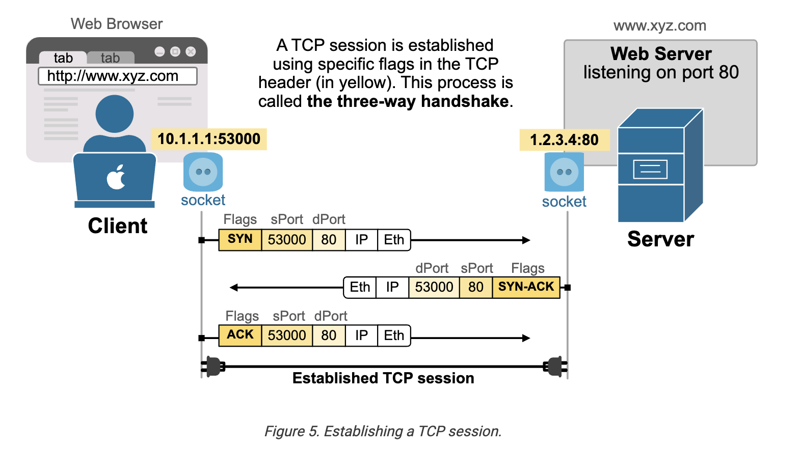
Establishing a TCP session
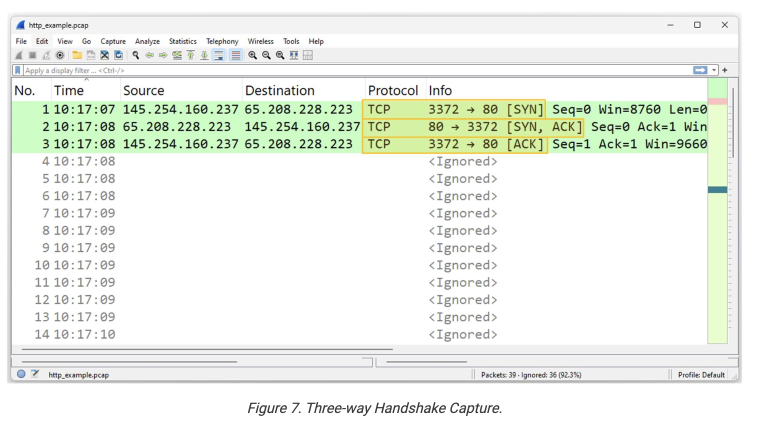
TCP provides end-to-end connectivity by establishing a TCP session that maintains the connection state at all times. It happens in three steps, called the three-way handshake:
- Step 1: The client that wants to initiate the connection sends a TCP message with the SYN flag set. This says, “I want to start a connection.”
- Step 2: The server responds with a TCP message that includes the SYN and ACK flags. This says, “I got your request and I’m ready too.”
- Step 3: The client sends a message with the ACK flag to confirm. This says, “We are connected.”
Once these three steps are done, the two hosts can start sending and receiving data. The process is visualized in the diagram below.
Providing reliability
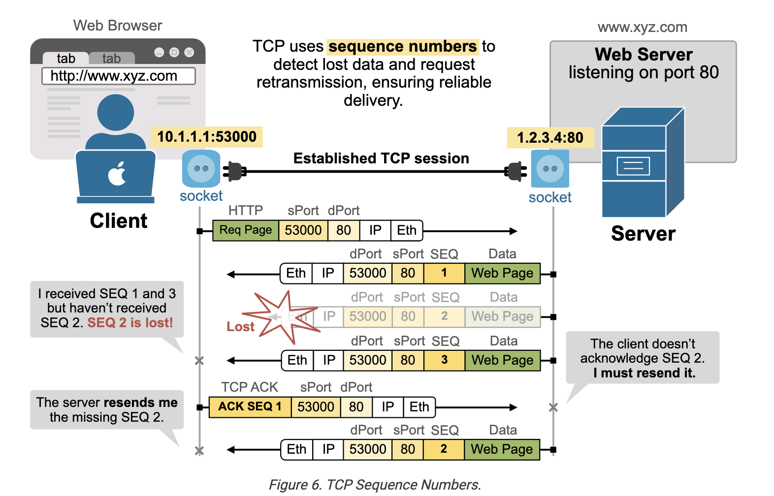 That’s why TCP includes a built-in method to make sure data is delivered successfully. Many applications need reliable delivery, so TCP was designed with an error recovery system. It does this using sequence numbers (SEQ) and acknowledgments (ACKs).
In the diagram above, the server sends the web page to the client in three TCP segments, each labeled with a sequence number (SEQ).
-
The client receives segments 1 and 3, but ==segment 2 is lost in the network==.
-
The client's TCP layer notices that segment 2 is missing (because it got 1 and 3, but not 2).
-
The client sends a message back to the server asking it to resend segment 2. This process enables TCP to detect missing data and request a resend, ensuring the application (such as a web browser) receives all the necessary information.
-
TCP flags are control bits in the TCP header that help manage the state and behavior of a TCP connection. Each flag has a specific role:
- SYN – Starts a connection.
- ACK – Acknowledges received data.
- FIN – Ends a connection.
- RST – Resets a connection.
- PSH – Tells the receiver to process data immediately.
- URG – Marks data as urgent.
-
These flags are used in different combinations to establish, manage, and close TCP connections.
-
A socket is made of an IP address and a port number. A pair of sockets identifies a unique TCP connection.
-
The client uses a random dynamic port number. For example, a web browser tab uses TCP port 61000 to initiate a connection to google.com.
-
The server uses a well-known port number registered by IANA. For example, a web server listens for connections on ports 80 and 443.
Network Layer
The Network Layer (Layer 3) of the OSI model is mainly responsible for ==routing and delivering packets== across networks using IP addresses.
The Transport layer (like the sender of a letter) handles the data and ports ==but relies on the Network layer to deliver it== (like the postal system).
Unlike the other OSI layers that have multiple protocols, layer 3 mostly depends on just one— the Internet Protocol (IP), which has developed into two main versions.
- ==IPv4 uses 32-bit addresses== and supports about 4.3 billion unique IPs.
- ==IPv6 uses 128-bit addresses==, allowing for a much larger number of IPs and improved network efficiency.
The Internet Protocol (IP)
The Network layer has two primary responsibilities:
- To insert the logical addressing into the message in the form of source and destination IP addresses.
- To deliver the message to the intended recipient based on the destination IP address.
The Internet Protocol (IP) has evolved through two main versions - IPv4 and IPv6
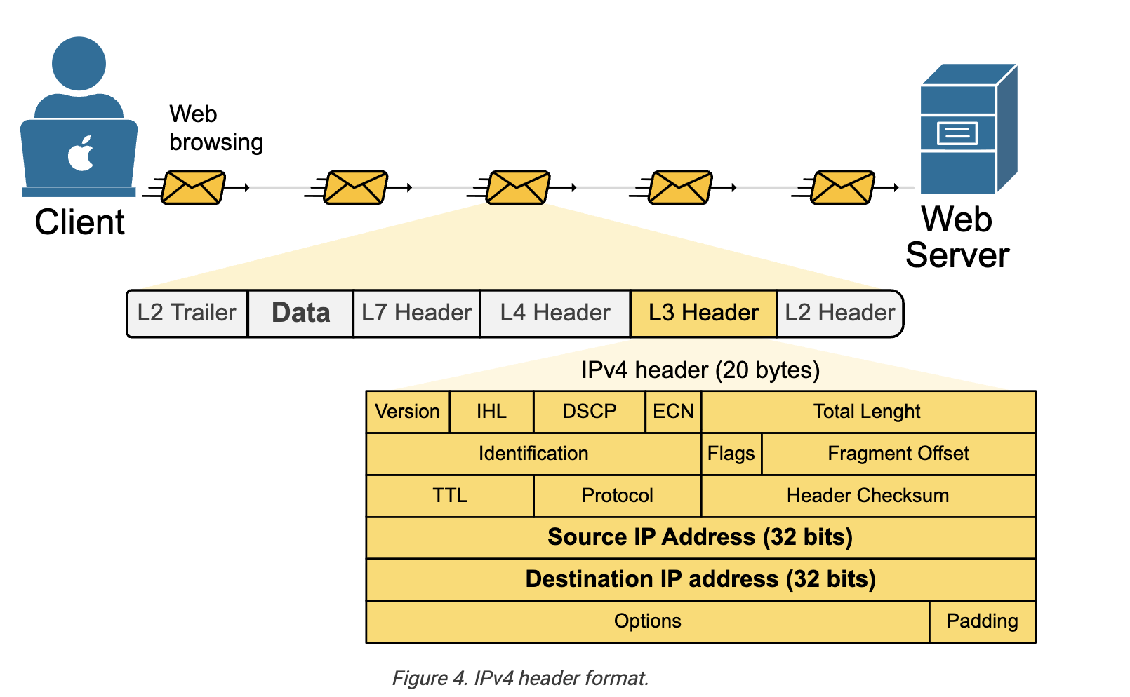
The IPv4 header is 20 to 60 bytes long and contains key information for the routing and delivery of packets. It includes 14 fields as shown in the diagram below. Each one has a specific role and provides important information to the network devices along the path.
What are IP addresses?
Every device on the network ==must have a unique IP address== The IP address identifies where a device is located and allows data to be sent to and from it, like a street address for computers.
- The destination IP address tells the network where the packet should go.
- The source IP address tells the network who originated the packet.
IP addresses are grouped into blocks (subnets)
Given an IP and subnet mask:
- Find the subnet mask and block size (magic number).
- Block size =
256 − last subnet mask octet.
- Block size =
- Locate the subnet range.
- Find which block the IP falls into.
- Determine the addresses.
- Network Address = first address in the block.
- Broadcast Address = last address in the block.
- Usable Host Range = addresses between network and broadcast.
- Calculate usable hosts.
- Host bits =
32 − prefix length. - Usable hosts =
2^(host bits) − 2.
- Host bits =
IP: 192.168.1.75/26
/26→ Mask =255.255.255.192- Block size =
256 − 192 = 64 - Subnets:
0, 64, 128, 192 75falls in the64–127block
Answer:
- Network Address:
192.168.1.64 - Broadcast Address:
192.168.1.127 - Host Range:
192.168.1.65 – 192.168.1.126 - Usable Hosts:
62
What is IP Routing?
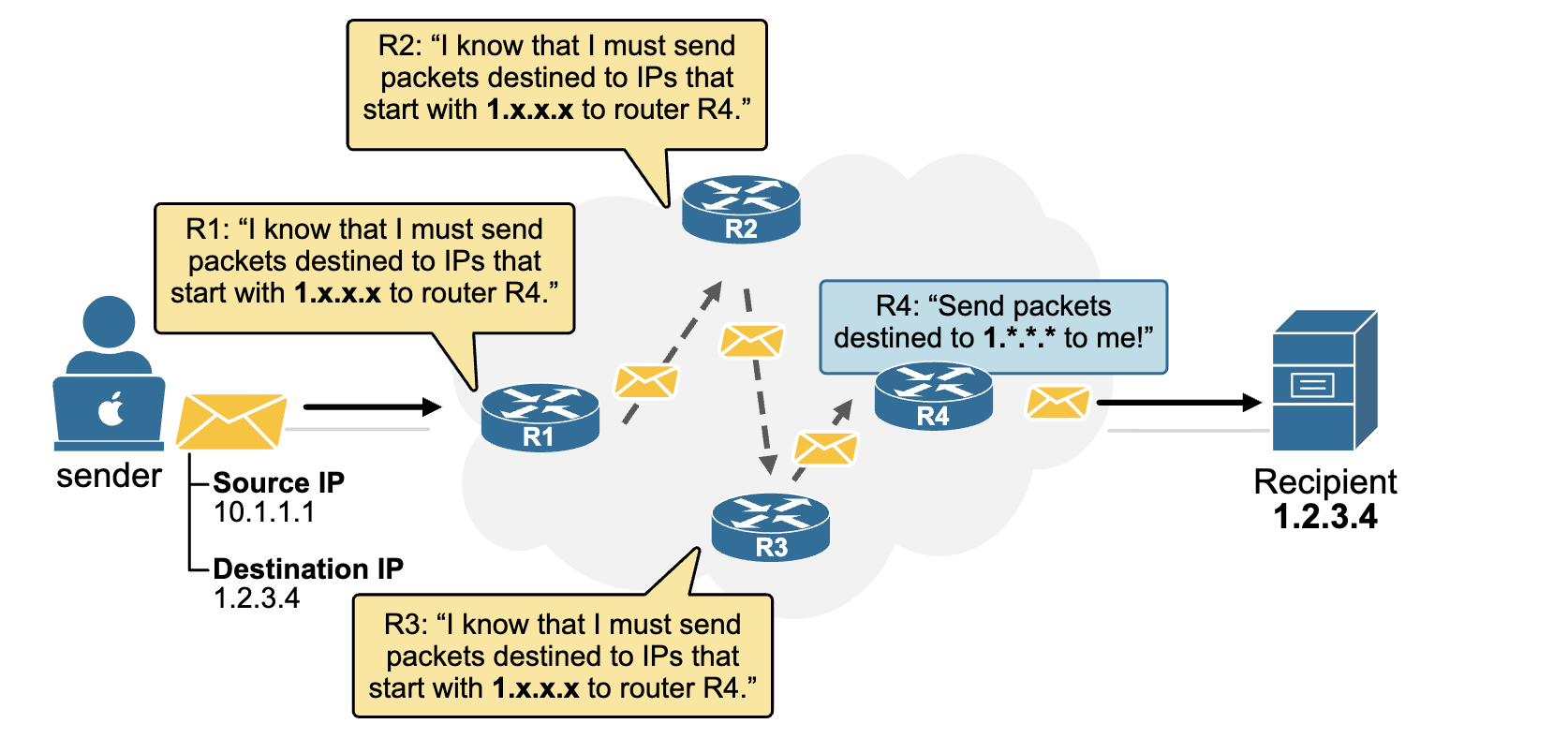
IP Routing is the process of finding the best path for an IP packet to travel from the source network to the destination network.
A switch can only forward data within the same LAN. To communicate with another network, you need a router.
A routing table is a database maintained by a router that stores destination networks and the next hop or outgoing interface used to forward packets.
The default gateway is the router a host sends packets to when the destination is outside its local network.
- Same network → Direct communication
- Different network → Send to the default gateway (router)
What is a Router?
You will often encounter the explanation that a router is a network device that ==operates at Layer 3 of the OSI model==. But what does that exactly mean - routers work at the Network layer?
It means that routers read the layer 3 header of packets and make forwarding decisions based on that information, as shown in the diagram below. That's why we say they operate at Layer 3.
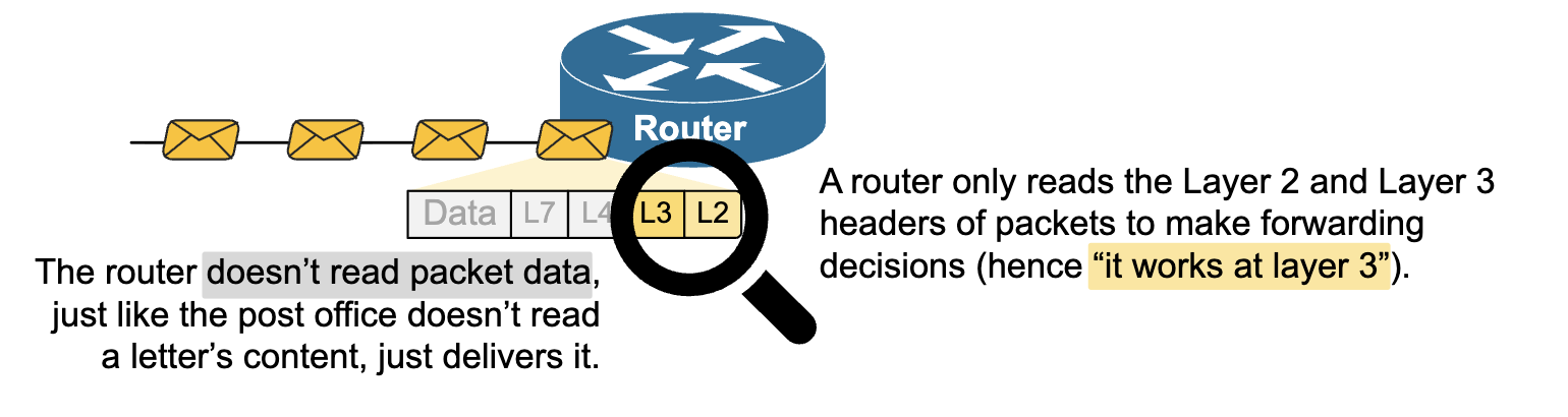
Figure 7. A router works at Layer 3.
Routers connect different IP networks and move packets between them. They read the destination IP address in each packet and decide where to send it next. Using routing tables, they choose the best path and forward the packet toward its destination.
Data Link Layer
ts main job is to move data between two devices that are directly connected at the physical layer. It adds framing, error detection, and MAC addressing. The physical layer then converts this data into electrical, optical, or radio signals and sends it over the medium.
Unlike Layer 3, which primarily uses the IP protocol, Layer 2 employs a variety of protocols. These protocols depend on the type of physical network being used. Some common Layer 2 protocols include 802.3 Ethernet, 802.11 Wireless (Wi-Fi), PPP (Point-to-Point Protocol), and HDLC (High-Level Data Link Control).
The Ethernet Header
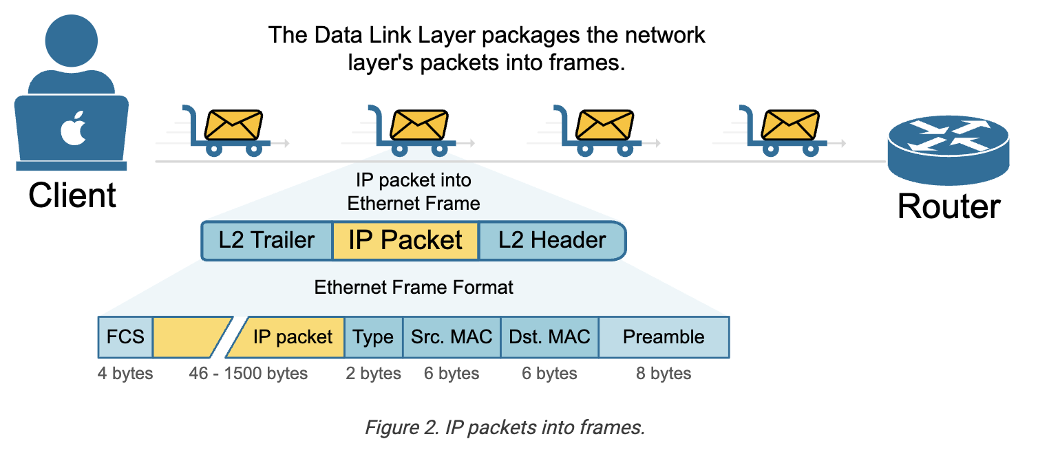
The data link layer adds a layer 2 header and a layer 2 trailer to the packet it receives from the Network Layer (Layer 3). This forms an Ethernet frame, as shown in the diagram below.
Framing
- Header - source & destination MAC address.
- Payload - the data from Layer 3 (e.g., the IP packet).
- Trailer - error-checking information.
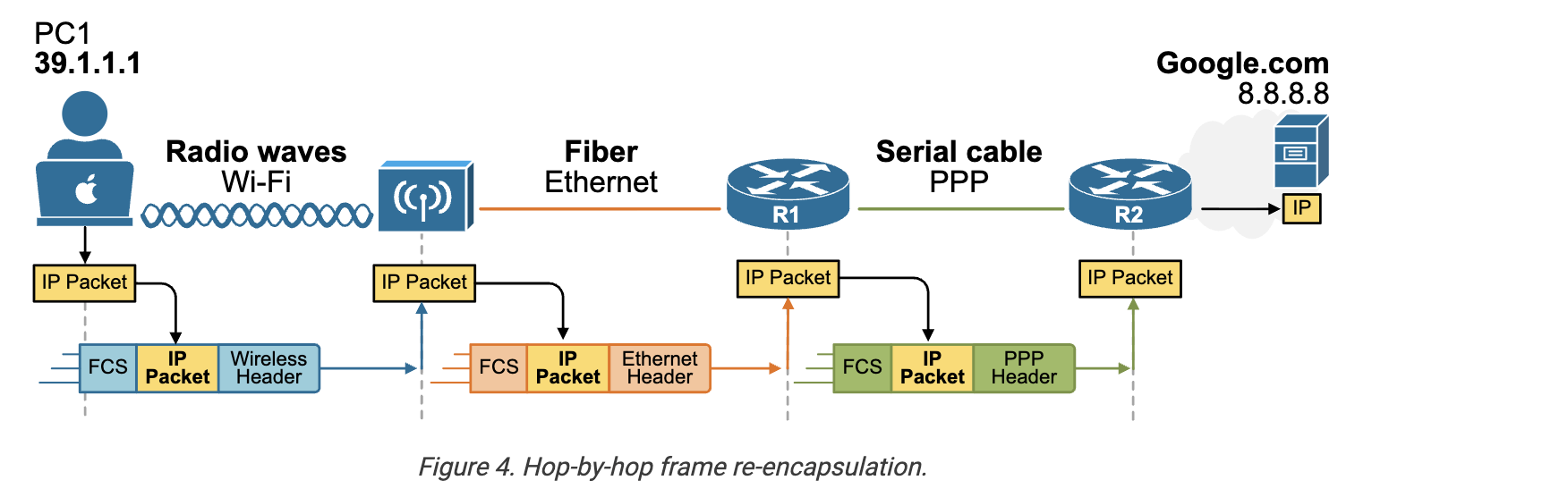
The wireless router receives the frame, removes the Layer 2 header and trailer, and keeps the IP packet inside. It then checks the destination IP address and decides where to send the packet next. To do that, it wraps the same IP packet in a new Layer 2 frame. This new frame is built for the next link — it uses the router's MAC address as the source and the MAC address of R2 as the destination.
At the next router, the same thing happens again. The frame is removed, the IP packet is checked, and then it’s placed in a new frame for the next hop. This continues until the packet reaches the final destination, which is PC2.
When Google's server receives the frame, it removes the Layer 2 information and sees that the IP packet is meant for it. Then it passes the data up the stack to the correct application.
Key Note: The IP packet ==stays the same== from start to finish, but the Layer 2 frame that wraps the packet ==is replaced at every router== to match the link between devices.
Data Link Sublayers
An important aspect of the data link layer is that it is not as independent as other layers of the OSI model. It works closely with the physical layer to move data across a network. The data link layer has two sublayers, as shown in the diagram below:
- Logical Link Control (LLC) sublayer.
- Media Access Control (MAC) sublayer.
The MAC sublayer is especially tied to the physical layer, as it controls how devices access the physical medium and how data is placed on the network.
The physical layer deals with the actual hardware. It defines things like cables and the electrical signals sent through them. The data-link layer adds rules for how that data should be sent over the physical connection.
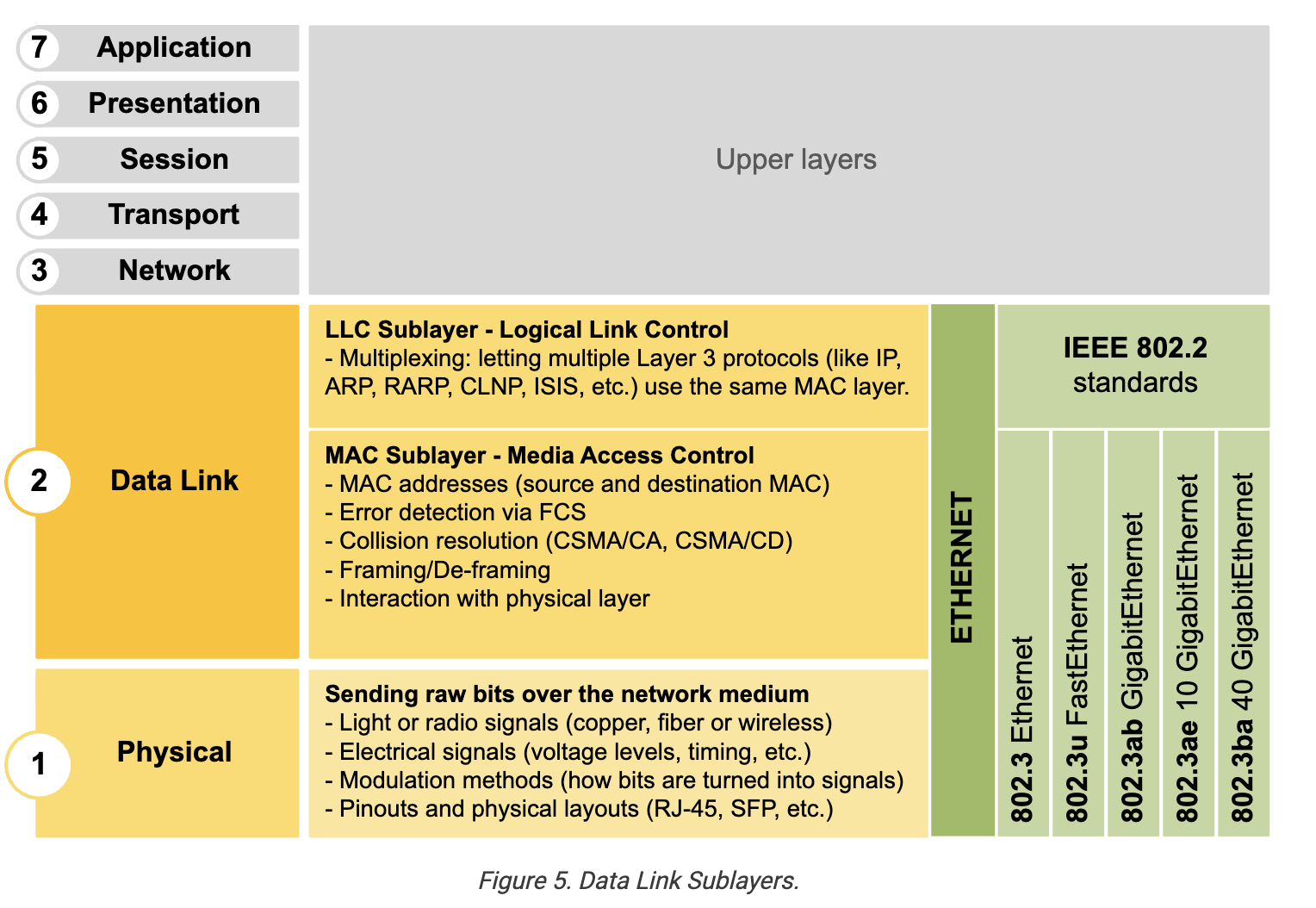
These two layers help deliver data from one device to another. When a computer or router wants to send an IP packet, it uses the data-link layer to get that packet to the next device in the path.
What are the MAC addresses?
At the Data Link layer, devices use MAC addresses to deliver data. Each network interface, like a network card or a router port, ==has its own unique MAC address==. Let's look at the following diagram, for example.
MAC address is 48 bits long and written in hexadecimal, like 00aa.bbcc.ddee
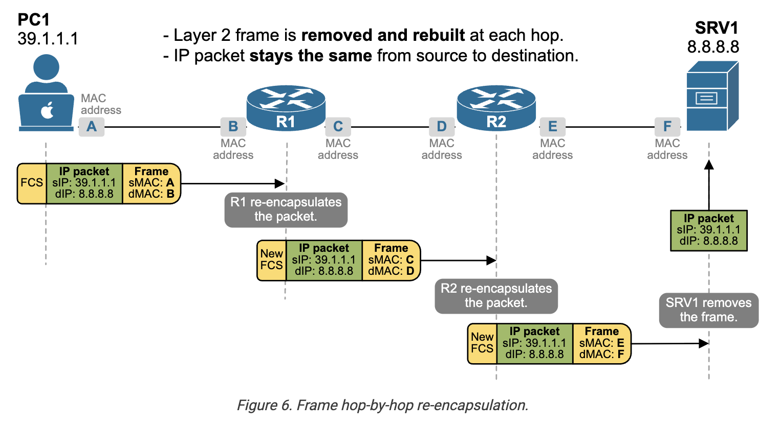
- At each router, the layer 2 frame is removed and rebuilt. This is called frame re-encapsulation.
- The source and destination MAC addresses change when the frame is re-encapsulated by every router.
- The IP packet (the layer 3 header) stays the same along the entire network path.
KEY NOTE: MAC addresses are used to deliver frames ==within the same local network== (Layer 2).
The layer 2 trailer
Let's look again at the example shown in the diagram above. The Layer 2 trailer is added at the end of each frame before it is sent over the network. Its main purpose is to help detect errors during transmission. The most common part of the trailer is the Frame Check Sequence, or FCS. The FCS contains a value calculated from the data in the frame using a method called CRC, or Cyclic Redundancy Check.
When the frame reaches the destination, the receiving device performs the same CRC calculation. It compares the result with the FCS in the trailer. If the values match, the frame is assumed to be correct. If they don’t match, it means the data was corrupted during transmission, and the frame is discarded.
The Layer 2 trailer is important for error detection but not for error correction.
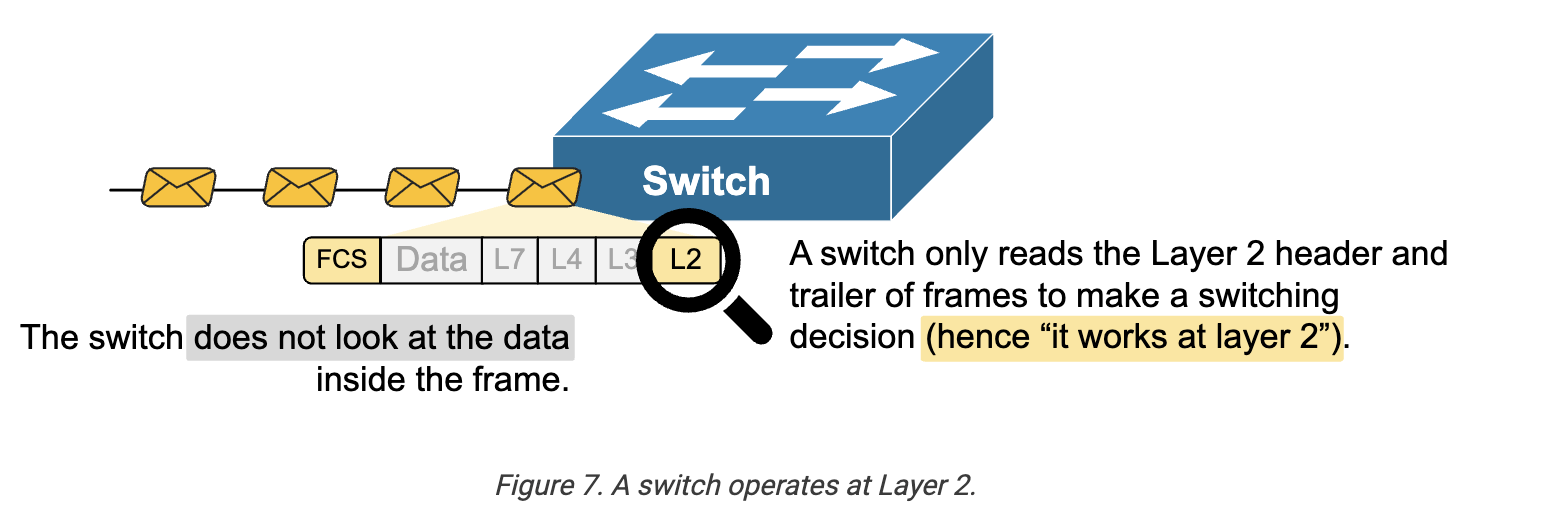
What is a Switch?
It means that switches read only the layer 2 header of frames and make switching decisions based on that information, as shown in the diagram below. That's why we say they operate at Layer 2.
Routers connect different IP networks and move packets between them. They read the destination IP address in each packet and decide where to send it next. Using routing tables, they choose the best path and forward the packet toward its destination.
Key Points :
-
The Data Link Layer (Layer 2) is responsible for local delivery between devices directly connected on the same network. It takes IP packets from Layer 3 and wraps them in frames that include a header and a trailer.
- The L2 header contains source and destination MAC addresses.
- The L2 trailer includes the Frame Check Sequence (FCS) used to detect transmission errors.
-
Unlike IP addresses, which stay the same across the entire network path, ==MAC addresses change at every hop==. Each router removes the old frame and adds a new one to move the IP packet to the next device. This is called frame re-encapsulation.
-
MAC addresses are only used within the local network. Routers forward packets based on IP addresses but re-encapsulate them in new Layer 2 frames for each link.
-
Ethernet is the most common Layer 2 protocol for wired networks. 802.11 Wi-Fi is standard for wireless networks.
-
==Switches operate at Layer 2== and use MAC addresses to forward frames between devices on the same network.
-
The Data Link Layer has two sublayers:
- Logical Link Control (LLC).
- Media Access Control (MAC).
-
The MAC sublayer ==manages access to the physical medium== and works closely with the Physical Layer. It is responsible for mechanisms like CSMA/CA and CSMA/CD, which we discuss in detail in the next course, part of our CCNA learning path.
-
Finally, the trailer at the end of the frame helps detect errors but doesn’t correct them. If the frame is corrupted, it is simply discarded.
-
ARP is generally considered a Layer 2 (Data Link Layer) protocol because it resolves IP addresses into MAC addresses for local communication. It acts as a bridge between the Network Layer (IP) and the Data Link Layer (MAC).
-
ARP protocol helps to find the MAC address of the device within the same network.
What is a Bit?
Computers and networks ultimately use bits to send data. A bit is the smallest unit of information — it’s either 0 or 1. However, networks are now unimaginably fast when transmitting data. When we talk about network speed, we measure how many bits are sent per second, but in scaled units as follows
- Bps (bits per second): the basic unit. Example: 1 bps = 1 bit every second.
- Kbps (kilobits per second): 1,000 bits per second.
- Mbps (megabits per second): 1,000,000 bits per second.
- Gbps (gigabits per second): 1,000,000,000 bits per second.
What is Byte?
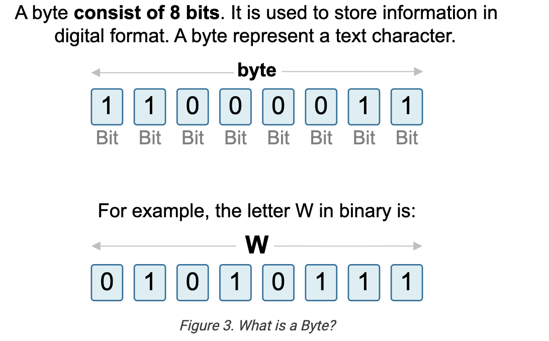
- 1 KB (Kilobyte) = 1,024 bytes
- 1 MB (Megabyte) = 1,024 KB = 1,048,576 bytes
- 1 GB (Gigabyte) = 1,024 MB = 1,073,741,824 bytes
- 1 TB (Terabyte) = 1,024 GB = 1,099,511,627,776 bytes
Latency and RTT
Latency is the time it takes for a packet to travel from source to destination. Delay is another word for the time taken. They are often used together.
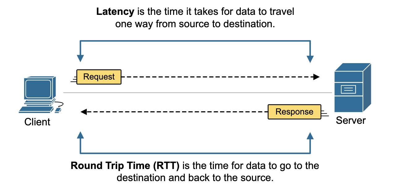
Round-trip time (RTT) is the time for data to go to the destination and back to the source.
Hub , Bridge and switch
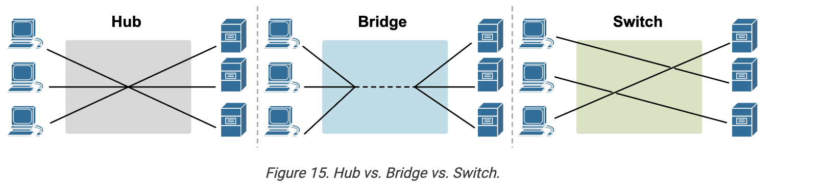
==Hubs== were the earliest way to connect multiple devices in a network, but they had major limitations. All devices shared the same collision domain, meaning only one device could send data at a time. As more devices were added, performance dropped. In summary:
- Works at Layer 1 (Physical layer)
- Forwards all data to all ports
- Creates one big collision domain
- No intelligence; no MAC address learning
- Only half-duplex communication
- Not used anymore
==Bridges== improved this by splitting a network into two smaller collision domains, reducing traffic and collisions. They understood MAC addresses and forwarded data more intelligently than hubs, but were still limited to just two ports. In summary:
- Works at Layer 2 (Data Link layer)
- Connects two network segments
- Reduces collisions by splitting the network
- Learns MAC addresses to forward frames selectively
- Limited to 2 ports (usually)
- Not used anymore - replaced by switches
==Switches== solved these problems by giving each connected device its own collision domain, eliminating collisions and improving speed and scalability. A switch uses MAC addresses to forward data only to the correct device, not to everyone, making communication much more efficient. In summary:
- Works at Layer 2 (some also support Layer 3)
- Each port is its own collision domain
- Learns MAC addresses and forwards frames intelligently
- Supports full-duplex communication
- Scalable, fast, and widely used in modern networks
To end devices, switches are invisible. They don’t interfere with communication — they simply forward frames behind the scenes. This is why, in most network diagrams, switches are often shown as a line or are not shown at all.
Routing
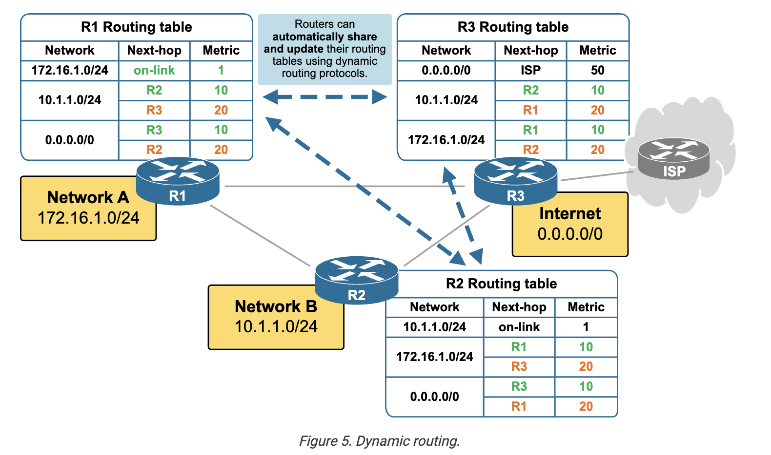
Routers forward traffic according to their IP routing tables. IP routing is the process of moving packets from one network to another using IP addresses as the “destination labels.” A router looks at the destination IP in each packet, checks its routing table, and decides the best path to send that packet toward its destination.
- Static routing is when an administrator manually configures routes. The router uses these fixed routes to forward packets, and they do not change unless the administrator updates them. This method is predictable and straightforward, but requires manual changes if the network topology changes.
- Dynamic routing uses routing protocols to learn and update routes automatically. Routers exchange information about network paths and choose the best routes based on metrics such as distance, cost, or speed. This makes dynamic routing more adaptable and efficient in larger or constantly changing networks.
Key Takeaways
- Switches operate at Layer 2 and forward frames within a single VLAN/subnet. They cannot connect different IP networks.
- Routers operate at Layer 3 and connect multiple IP networks by reading IP headers and using routing tables to forward packets.
- Hosts make the first routing decision: if the destination is outside the local subnet, they send the packet to their default gateway (a router). if not then use ARP and send the packets.
- IP routing can be ==static== (manually configured routes) or ==dynamic== (routes learned via routing protocols).
- Layer 3 switches combine ==switching and routing in one device==, enabling high-speed inter-VLAN routing directly in hardware without relying on external routers.
Firewall
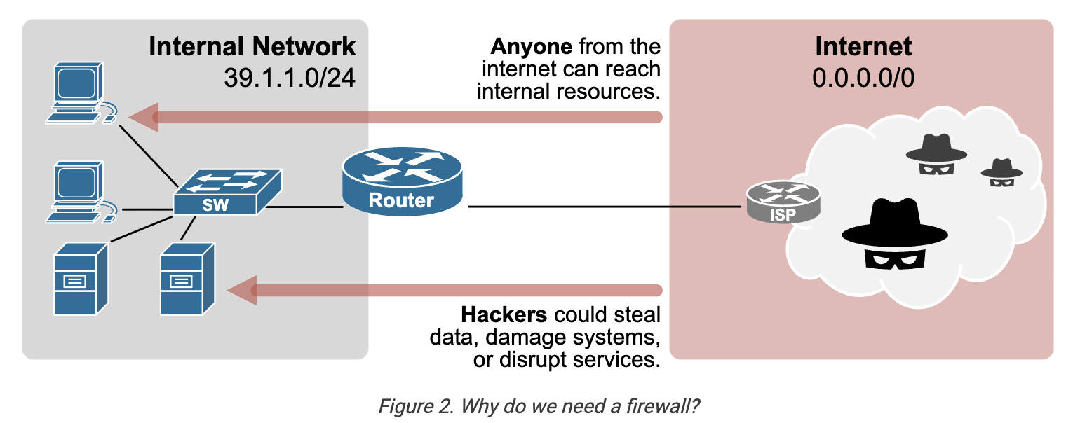
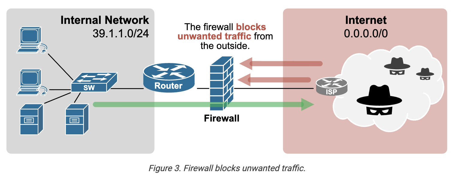
With firewall rules only trusted traffic is allowed.
How it works ?
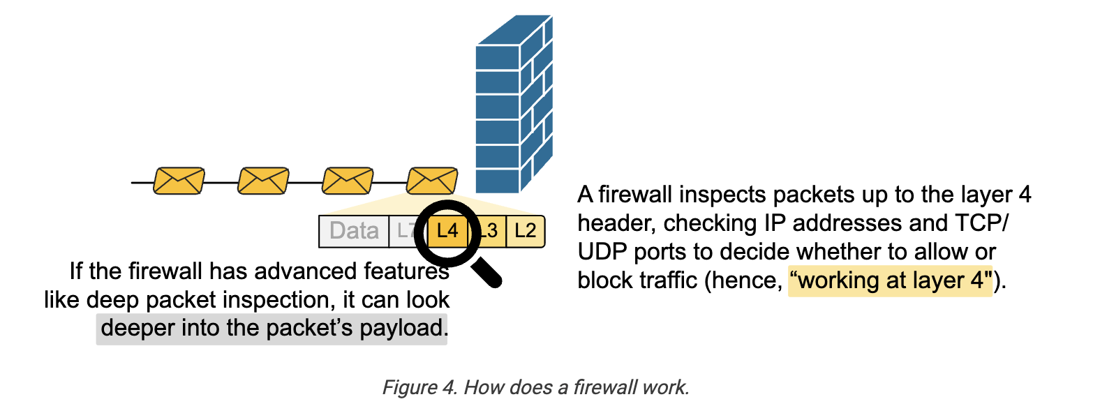
- It separates the network into zones, usually ==inside (trusted)== and ==outside (untrusted)==, and can also include intermediate zones like a DMZ.
- Firewalls can be placed at the perimeter to filter Internet traffic or inside the network to segment and protect sensitive areas.
Load Balancers
Operate at the Layer 7 of the OSI model.
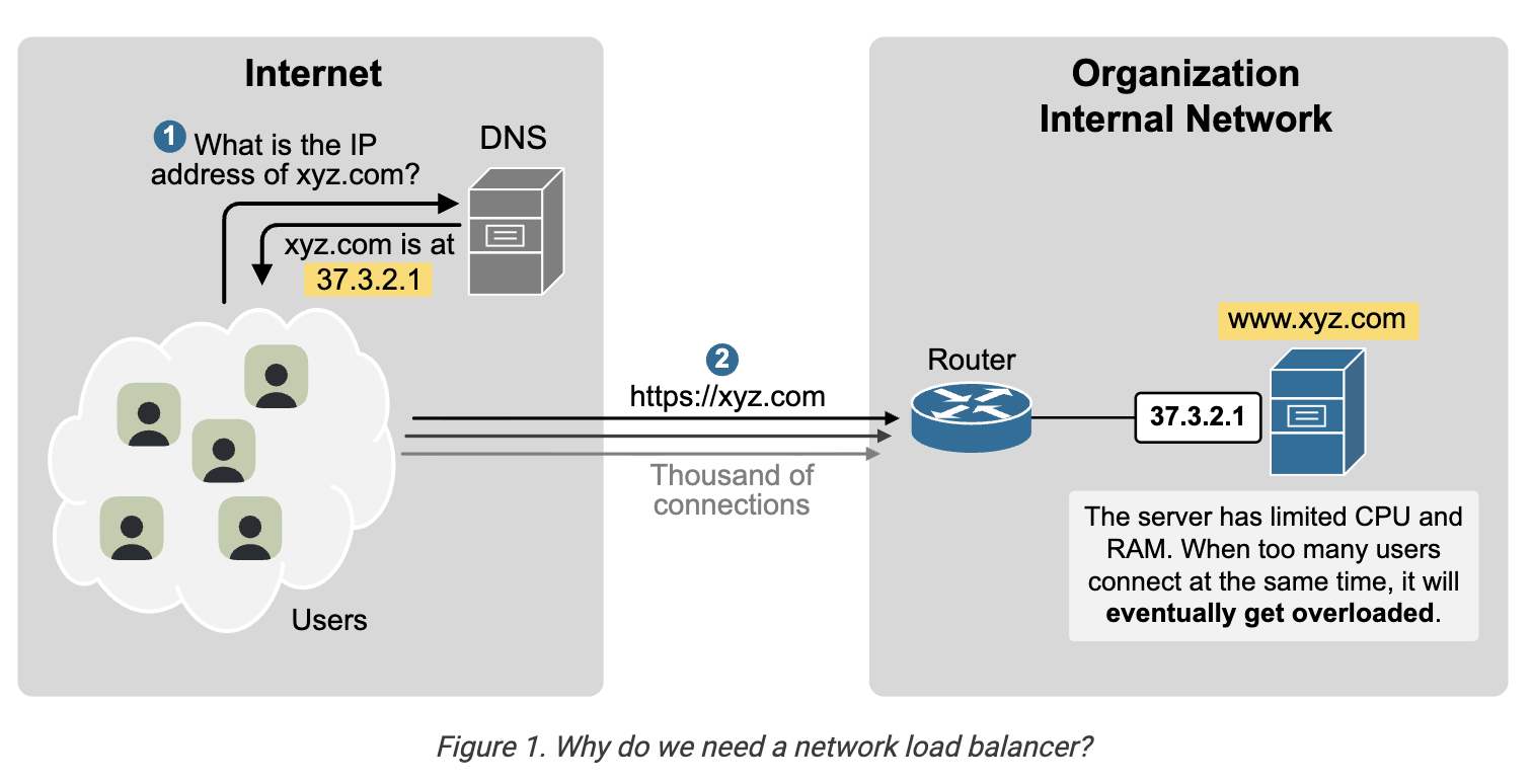
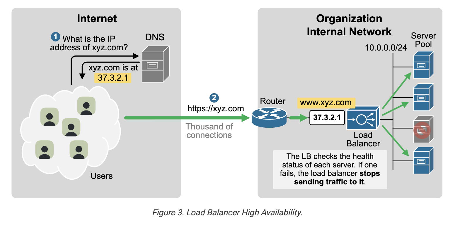
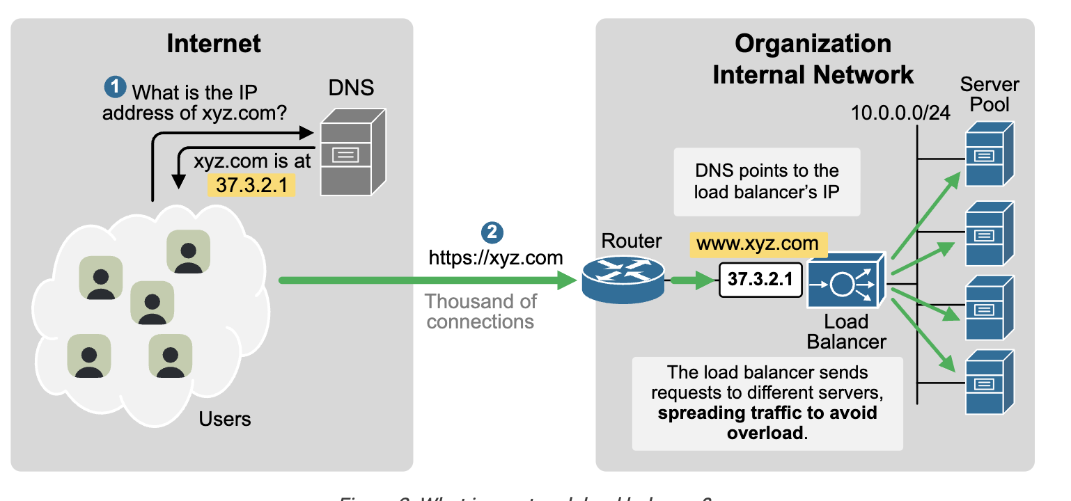 The solution is to place the e-commerce web app's IP address on the load balancer. ==DNS points to the load balancer’s IP==. All user HTTPS connections terminate at the load balancer. It then forwards each incoming connection to one of the backend servers. This spreads the traffic across all servers, preventing any single server from getting overloaded.
Proxy Server
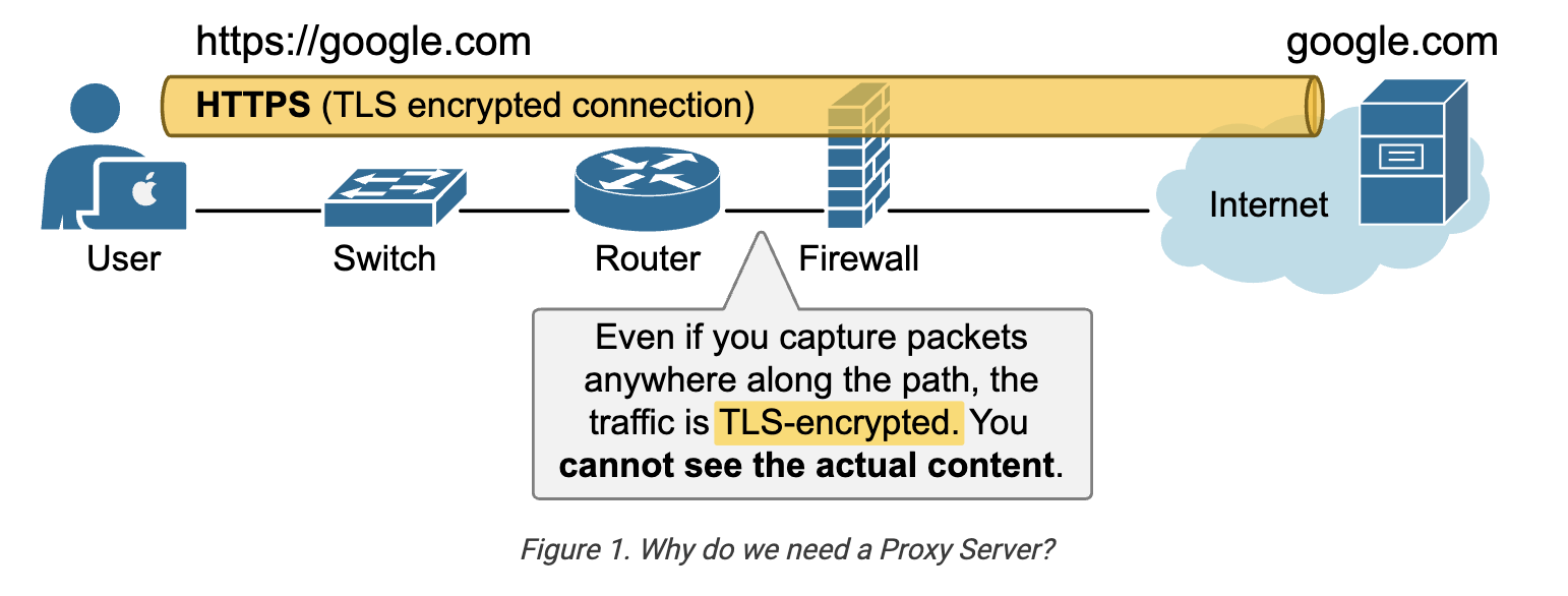 here firewall cant read the content that is encrypted by TLS.
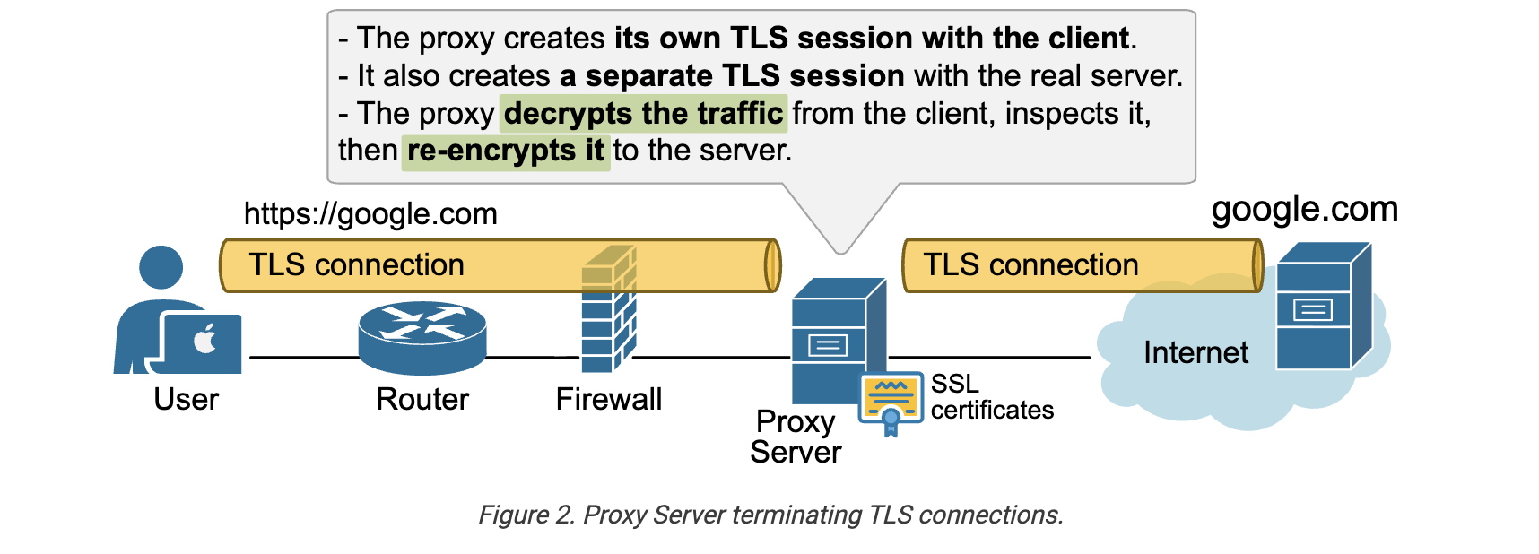
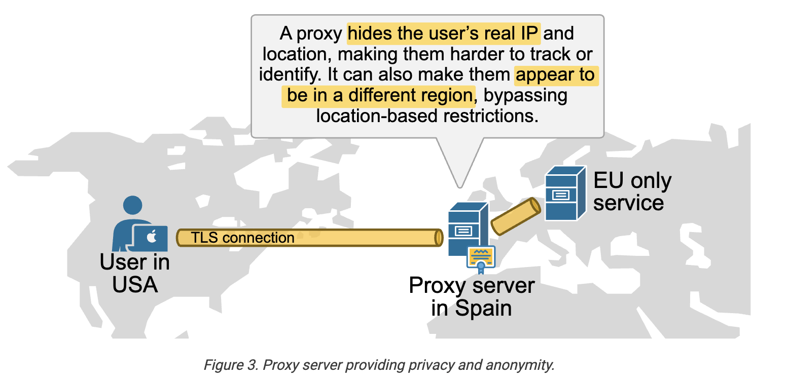
Proxy also provide privacy can hide the client IP address from the outside server.
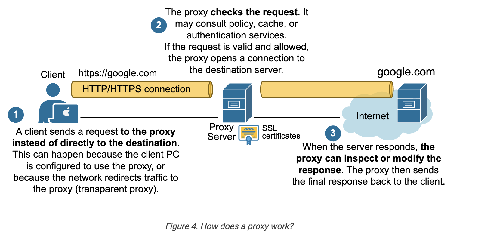
How does proxy work ?
Types of Proxy
- ==A forward proxy== represents one or more CLIENTS to the outside world. It handles outbound requests and can enforce corporate policies.
- ==A reverse proxy== represents one or more SERVERS to outside clients. It handles inbound requests and can provide load balancing, TLS termination, and web application security.
Also, proxies can be classified as explicit or transparent depending on whether clients know that the proxy exists or not:
- ==In explicit mode==, clients are explicitly configured to use the proxy. Clients know the proxy exists in the network path. Every modern OS allows you to configure a proxy IP, and every modern web browser does.
- ==In transparent mode==, the network redirects traffic to the proxy without client configuration. Transparent proxies are convenient but can complicate TLS inspection and client authentication.
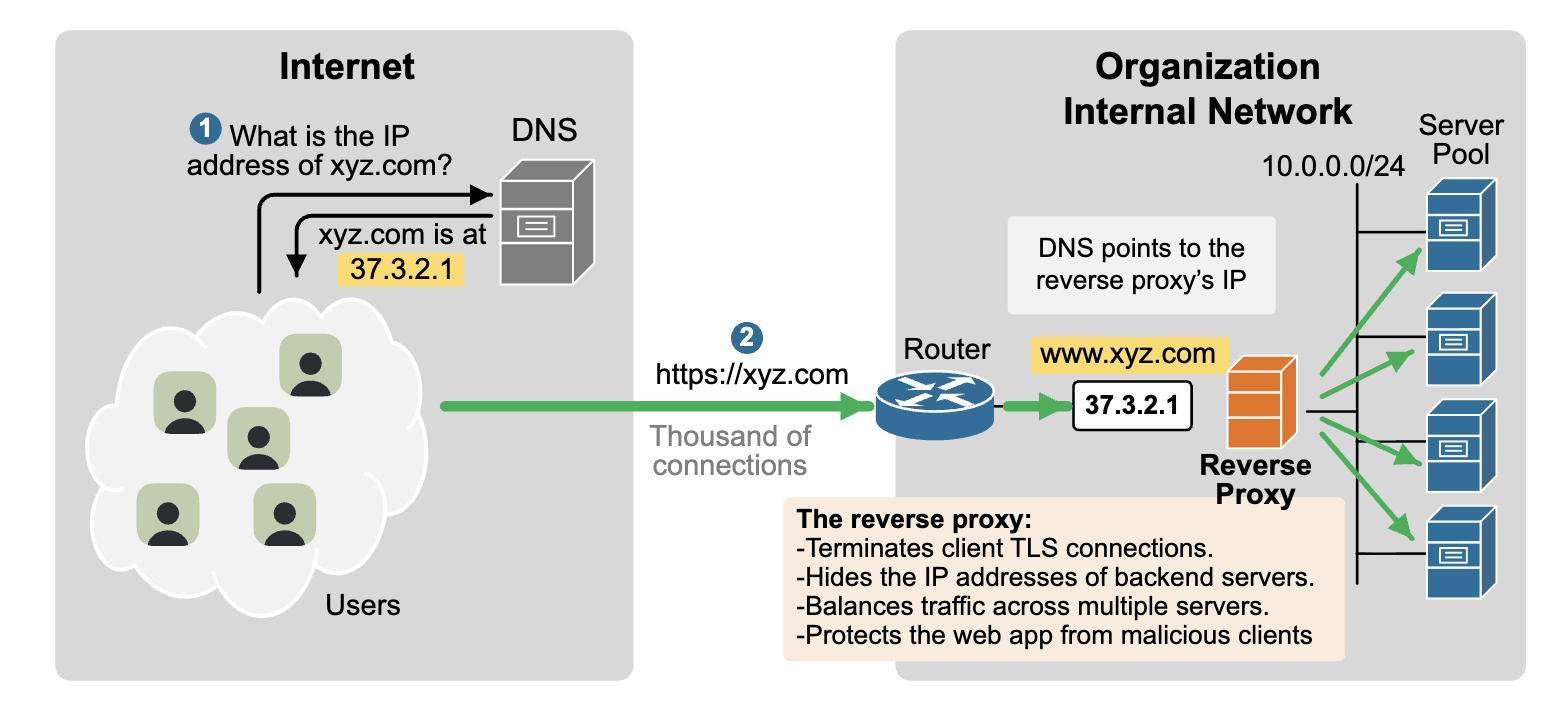
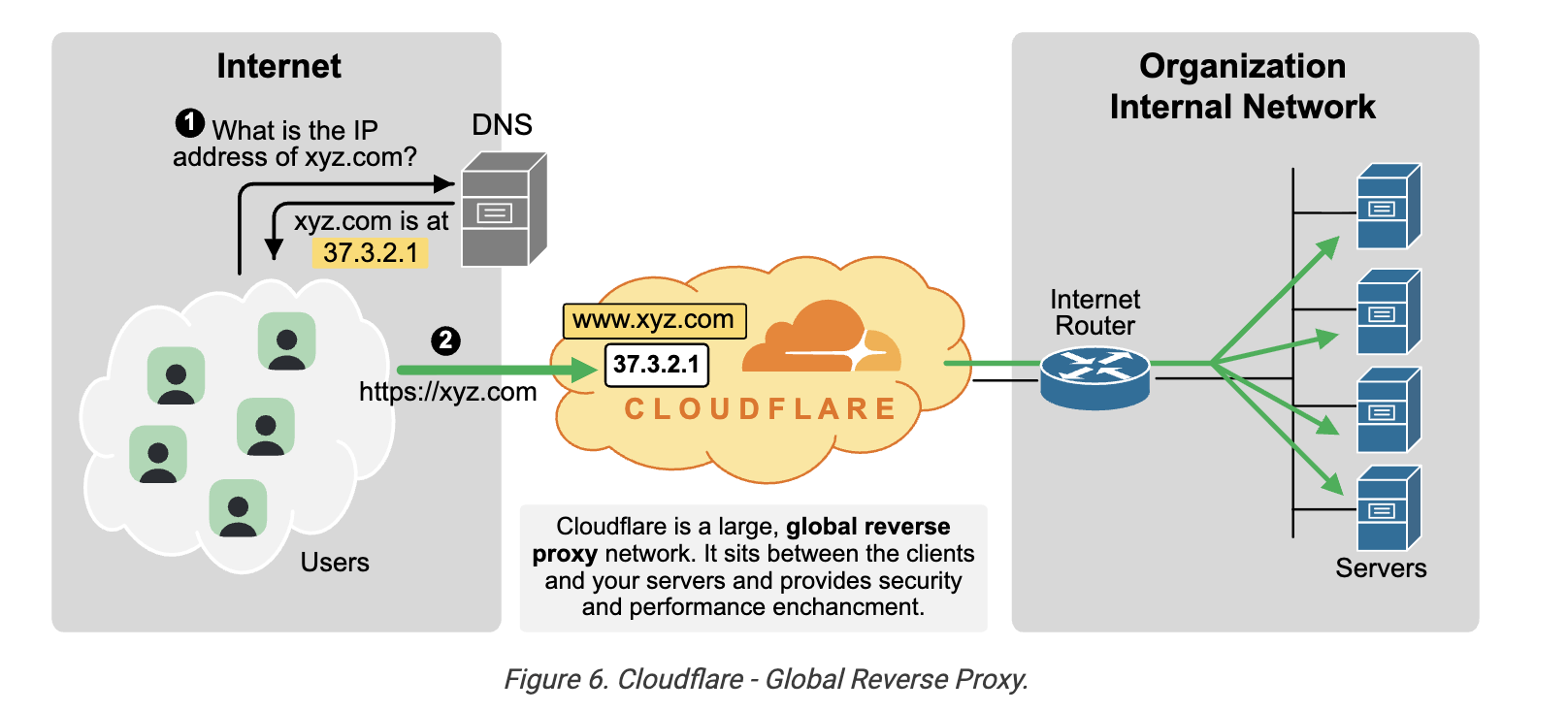 ==In today’s AI world==, most Internet traffic comes from bots and automated AI agents, making it harder than ever to stop DDoS attacks and bot floods. By using Cloudflare (or another cloud-based reverse proxy), organizations can offload key security and performance tasks to a provider that specializes in them, including:
- Defending against attacks like DDoS
- Speeding up websites with caching and a global CDN
- Securing traffic with firewalls, SSL, and bot protection
- Boosting availability through smart traffic routing
Key Takeaways
- A proxy is ==a middleman== between clients and servers, relaying requests.
- Proxies improve security by decrypting and inspecting TLS traffic.
- They provide ==privacy== by hiding client IPs and bypassing geo-restrictions.
- Proxies boost performance with caching to reduce bandwidth use.
- Forward proxies control outbound access.
- Reverse proxies protect inbound servers.
- Cloud-based reverse proxies (e.g., Cloudflare) ==add global security and speed==.
- Reverse proxies and load balancers overlap but serve different specialized roles.
Proxies mainly work at the application layer. They understand the protocol being used.
==How Packet Travels ? == When a user enters a URL, DNS converts the domain name to an IP address. The computer checks whether the destination is on the local network. If not, it uses ARP to find the default gateway's MAC address, encapsulates the data with TCP, IP, and MAC headers, and sends it to the router. Each router reads the destination IP, consults its routing table, forwards the packet to the next hop, and this continues until the destination server receives it. The server processes the request and sends a response back.
==What is an API Gateway?== An API Gateway is a single entry point for client requests in a microservices architecture. It routes requests to the appropriate service and provides features like authentication, rate limiting, load balancing, logging, and request transformation.
Router sends packets between networks. API Gateway sends API requests to the correct backend service.
==NIC == A NIC is the hardware that connects a device to a network, and the MAC address is the unique physical address assigned to that NIC for communication on the local network.
==Important Points==
-
SSL/TLS encrypts data between the client and server to provide secure communication. Used by HTTPS. Prevents hackers from reading your data.
-
Vertical scaling : Increase the power of one server.
-
Horizontal Scaling : Add more servers instead of upgrading one server.
-
Caching stores frequently used data in fast memory so future requests are served quickly. Instead of querying database each time.
-
A Virtual IP (VIP) is a shared IP address used by multiple servers through a load balancer. Users see one IP, but requests may go to many servers.
-
REST API : REST is a design style for building web APIs that usually uses HTTP methods like GET, POST, PUT, and DELETE.
-
A container packages an application with all its dependencies so it runs the same everywhere.
-
A VPN creates an encrypted tunnel between your device and a VPN server, protecting your internet traffic.
-
Multiplexing : Multiplexing combines multiple signals into one communication channel to use bandwidth efficiently.
-
Modem : Connects your home to the ISP.
-
Router : stributes the Internet connection to multiple devices.Connects different IP networks.
-
Gateway : Connects networks using different protocols.
-
A subnet mask separates the network portion and host portion of an IP address.
-
NAT (Network Address Translation) converts private IP addresses into public IP addresses so multiple devices can share one Internet connection.
-
Packet switching breaks data into small packets, sends them independently, and reassembles them at the destination. Used by the Internet.
-
Congestion occurs when network traffic exceeds the network's capacity, causing delays and packet loss.
-
A CDN (Content Delivery Network) stores copies of website content on multiple servers worldwide so users receive data from the nearest server. Benefits: - Faster loading - Lower latency - Reduced server load
-
Cookies are small files store==in the browser== that remember user information like login sessions and preferences.
-
A session stores user information on the ==server ==during a user's interaction.
- WebSocket provides full-duplex communication between client and server over a single connection. Used for: - Chat Apps - Live Games - Stock Market Updates